In addition to tools to process surface geometry into toolpaths for cutting, ArtCAM has built into it a series of basic design and editing tools for creating those surface reliefs from scratch. ArtCAM can work in both Raster and Vector modes to generate reliefs. This page will look at only working with Vector editing to get the basec concepts down.
To create a relief model from scratch in ArtCAM, we must first create a new model. Set the size of the model in Width and Height (this is not thickness of the stock material in Z - that will be defined later.)
With the new model, we have a blank slate upon which to begin creating relief geometry.
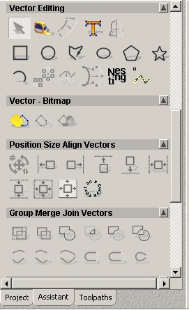
In the Control Pane on the left hand side of ArtCAM, scroll down until you find the Vector Editing tools. These tools allow us to define parametrically controlled graphic objects that will drive the creation of three-dimensional geometry.
The basic set of tools here includes rectangles, circles, polygon shapes of various freeform and constrained types, etc. There are also tools further down for creating sweeps, revolutions, extrusions, etc. All tools are completely parametric and can be editing, stacked, and nested.
For a basic example, choose the rectangle tool, and in the 2D view, draw two simple rectangular shapes.
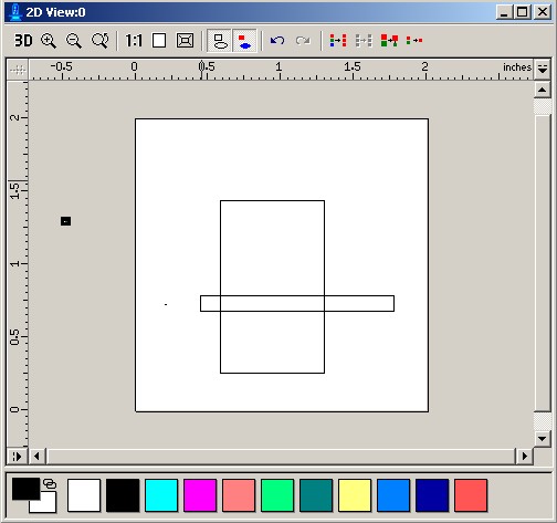
Once you have these shapes, choose one of them with the mouse, then double click on it. Make sure that you do in fact have the rectangular shape selected, not the background.
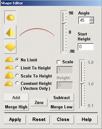
When you double-click on the shape, the Shape Editor window appears allowing you to establish how this shape will be treated in Three-dimensions.
There are different types of relief - from rounded to pyramid to flat - and you can establish angular restraints and height restraints for the relief. All of these in some fashion bring the rectangular shape up into three-dimensions to create a surface condition.
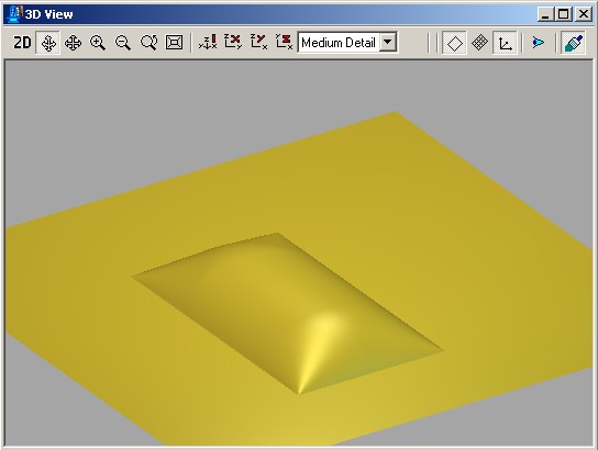
The rounded profile 45 degree angle form shown here results in the following relief when added to the model (hit Add to generate it).
Where this approach becomes more interesting is when we combine multiple shapes into a single composite relief. Quite a bit of flexibility is added to parametric surface creation when using the tools in this manner. The following are different modes of combining vector shapes in relief. Play around with them to achieve different results.
Add - Mathematically adds the heights of the new relief
to those of the old. This effectively combines the two using logical addition
of surface geometry. You'll have to try it to really see what this does.
Subtract - Mathematically subtracts the heights of the
reliefs - the exact inverse of Add.
Merge High - This method compares the two relief files,
and for every area of the relief, will use whichever one is the higher
of the two. This is more equivalent to the typical Boolean Union within
most CAD systems.
Merge Low - Similar to Merge Highest, but uses whichever
hieght is lower. Effectively this is similar to a Boolean Subtraction.
Zero - Zeros out the height of the relief, returning
it to a completely flat, two-dimensional plane. Essentially this resets
the relief.
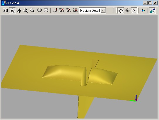
The relief below was achieved by combining a flat rectangle of a start height in the negative values (below the surface) with the original rounded relief shown above. The two are combined with a Merge Low operation to ensure that the low value of the thin rectangle takes precedence over the rounded relief above the surface.
Once you have a surface generated, you can then proceed to Generating Machining Toolpaths in ArtCAM