Importing a Surface using ArtSurface

The first step to creating and machining a 3D relief using ArtCAM is getting the geometry file into the ArtCAM software. Because we have built the file in a CAD system, such as MicroStation, AutoCAD, formZ, or something similar, we must pass through some more general translation formats to get the geometry into a machinable state.

There are a few formats that can be used to perform this translation, such as DXF and IGES, but the most effective for our purposes is the IGES file format. This format best preserves the full surface geometry.

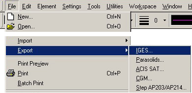
Using MicroStation CAD as an example (though similar functionality and screens would be available from other CAD programs) we simply EXPORT the geometry into the IGES file format. This is a fairly straightforward export, presuming your geometry is correct.

To achieve the best results when exporting, make sure that the following are true:

  1. The geometry is the only thing in the CAD file. Extra geometry, even on layers that are turned off, will show up in the IGES export, and might throw off the process within ArtCAM. If you need to do so, simply copy the desired geometry into a new file. MicroStation's Edit/Copy command can do this, along with the FF= keyin command. AutoCAD's Edit/Copy or Writeblock command will do the same.
  2. The geometry is at true machining scale, in inches or millimeters. You cannot "print-to-scale" using CAM software. The object must be at real world scale to work propery.
  3. The geometry is at or near the 0,0,0 global origin point of the CAD file. This will make setting up machining a bit easier. You can simply move the geometry to the 0,0,0 point in your CAD file if necessary.


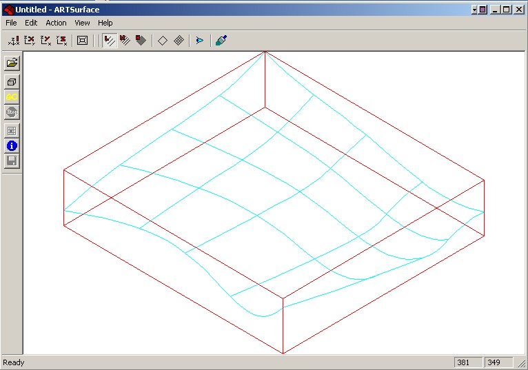
Now start the program called ArtSurface, found within the ArtCAM folder in the Start menu. ArtSurface is a translation intermediary between the CAD software and the CAM software. It will convert our IGES surface into a relief file.

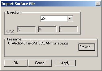
Within ArtSurface, choose File then Import, and the dialog as shown on the left will appear.

Choose the Browse button to find your .igs file and hit OK. Make sure to leave the Direction set at Z+. This will ensure proper orientation of the surface file for most circumstances.

The surface has now been brought into ArtSurface, and you should see it (blue), along with its Bounding Box (red). The bounding box controls the overall extents of the relief model.

There are some circumstances in which the Bounding Box does not completely encompass your surface and thereby cuts off a part of it. This usually happens on either the top or the bottom. If this occurs, click on the icon and adjust the size of the box until the entire surface is surrounded.


Next, click on the GO button in the left side panel to process the surface and create a relief. ArtSurface will show you onscreen some form of surface-path description, as shown below, that represents the surface geometry.

The final step in the translation process is simply to save out the surface geometry as a Relief (.rlf) file for ArtCAM to open.

Choose Save As from the File menu, and save out this file.


Loading the Relief into ArtCAM

Once you have the Relief (.rlf) file created, you can now open this in ArtCAM for further processing.

Launch ArtCAM from the Start Menu, and in the control panel on the left of the screen, Create a New Model (right).

Choose the size of the model in plan (you will set the thickness later), and teh appropriate units (inches or metric), and a new model space will appear with a blank plate of no relief.

Next, in the control panel on the left of ArtCAM, find the Relief Operations tools, and choose the first tool, Load Relief.


The Load Relief select the relief file that you have just created using ArtSurface, and select OK.

The Load Relief dialog box (at left) will then appear, asking yoy the mode that you will use to bring in the relief.

Since we are not combining this relief file with an existing relief model, we will simply apply this by Pasting. If you were combining multiple reliefs, you would need to choose the method of combining them. The methods are as follows:

Replacing - Replaces the old model with the new.
Adding - Mathematically adds the heights of the new relief to those of the old. This effectively combines the two using logical addition of surface geometry. You'll have to try it to really see what this does.
Subtracting - Mathematically subtracts the heights of the reliefs - the exact inverse of Add.
Merge Highest - This method compares the two relief files, and for every area of the relief, will use whichever one is the higher of the two. This is more equivalent to the typical Boolean Union within most CAD systems.
Merge Lowest - Similar to Merge Highest, but uses whichever hieght is lower. Effectively this is similar to a Boolean Subtraction.
Pasting - A simple pasting operation, usually performed onto a blank relief as we are doing here.


A few more options when bringing in the relief model allow you to size and position the relief onto your ArtCAM model.

In most circumstances, you will not need to modify these parameters at all. If you do, be clear what you are doing with them.

In our case here, just hit Paste to complete the operation.

The surface geometry is now ready for the next step, Generating Toolpaths in ArtCAM.